Hola,
Soy un novato aquí.
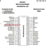
Estoy tratando de hacer todo PORTA y PORTE como un pin analógico, ¿podría alguien aquí guiarme sobre cómo configurarlo, qué necesito para agregar el pin AN5 para conectarlo como un pin de temperatura?
Hasta ahora lo que hice a continuación:
Gracias.
Soy un novato aquí.
Estoy tratando de hacer todo PORTA y PORTE como un pin analógico, ¿podría alguien aquí guiarme sobre cómo configurarlo, qué necesito para agregar el pin AN5 para conectarlo como un pin de temperatura?
Hasta ahora lo que hice a continuación:
Código:
'****************************************************************
'*  Name    : Temprature with ADC .BAS                          *
'*  Author  : [Isario]                                          *
'*  Notice  : Copyright (c) 2021 [ISR]                          *
'*          : All Rights Reserved                               *
'*  Date    : 10/16/2021                                        *
'*  Version : 1.0                                               *
'*  Notes   :                                                   *
'*          :                                                   *
'****************************************************************
;-------------------------------------------------------------------------------
;**** Added by Fuse Configurator ****
; Use the Fuse Configurator plug-in to change these settings

Device = 16F877A
Declare Xtal = 8
Config FOSC_XT, WDTE_OFF, PWRTE_ON, BOREN_ON, LVP_ON, CPD_OFF, WRT_OFF, DEBUG_OFF, CP_OFF

;**** End of Fuse Configurator Settings ****
;-------------------------------------------------------------------------------


All_Digital =true

Declare LCD_Type 0
Declare LCD_DTPin PORTD.4
Declare LCD_ENPin PORTD.1
Declare LCD_RSPin PORTD.0
Declare LCD_Interface 4
Declare LCD_Lines 4
Declare Float_Rounding = On
Declare Float_Display_Type = LARGE

Declare Adin_Res = 10
Declare Adin_Tad = FRC
Declare Adin_Delay = 120


ADCON1 = %10000000; //Right Justify, FRC Clock , All pins as Analog Input and setting Reference Voltages
ADCON0 = %10000001; //Turn ON ADC and Clock Selection
ADRESH = 0;
ADRESL = 0;


ADCON0.ADCS0=0; // ADCS0, ADCS1 & ADCS2 together determines the clock speed
ADCON0.ADCS1=1; // if 0 1 1 then speed is Fosc/64
ADCON1.ADCS2=1;

ADCON0.CHS0=0; // CHS0, CHS1 & CHS2 together determine the pins
ADCON0.CHS1=0; // if 0 0 0 then the pin used is RA0/AN0
ADCON0.CHS2=0;

ADCON0.ADON=1; // enable A/D converter
ADCON1.ADFM=1; // declares 10 bits consisting of 8 bits ADRESL and 2 bits ADRESH

ADCON1.PCFG0=0; // PCFG0, PCFG1, PCFG2 & PCFG3 together determine
ADCON1.PCFG1=0; // whether the pin is used as an analog input or a digital input
ADCON1.PCFG2=0; // if 0000 then all pins as Analog input
ADCON1.PCFG3=0;


TRISA = %11111111
TRISB = %11100000
TRISC = %00000000
TRISD = %00000000
TRISE = %111
Gracias.


