Para los que quieren aprender y diseñar circuitos de potencia con control de fase
 9.5.2 Ramp-and-Pedestal Control
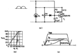
Both high gain and linearity are obtained by charging C1 from the undamped sinusoidal waveform, as in Figure 9.32(a).
This adds a cosine wave to the linear ramp to compensate for the sinusoidal supply waveform, resulting in the linear
transfer characteristics shown in Figure 9.32(b).
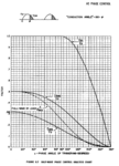
System gain can be adjusted over a wide range by changing the magnitude of charging resistor, R2, as indicated in
Figure 9.32(c).
By selecting a ramp amplitude of one volt, for example, and assuming a zener diode of 20 volts, then a change
in potentiometer setting of only 5 percent results in the linear, full-range change in output.
The values shown in Figure 9.32(a) are typical for a 60 Hz circuit.
The potentiometer resistance must be low enough to charge capacitor C1 rapidly, in order to be able to
trigger early in the cycle. This is the limiting factor on control impedance level.
The logarithmic characteristic of diodes limits the control gain that can be achieved with a
reasonably linear transfer characteristic.
At a one-volt ramp amplitude, diode non-linearity is not pronounced, but a 0.1 volt ramp voltage, the
capacitor is charged primarily by diode current, thus obliterating the cosine-modified ramp

FIGURE 9.32 RESISTANCE CONTROllED PEDESTAL WITH COSINE-MODIFIED RAMP
The sharper knee of a zener diode may be used
to obtain higher gains, at the expense of requiring a higher voltage
across the potentiometer. The third limiting factor is the peak-point
current of the unijunction transistor. This current must be supplied
entirely by R2 and should be no higher than one-tenth the charging
current on C1, at the end of the half-cycle, in order to avoid distortion
of the waveform.
Del clásico libro de GE .. SCR manual ..Lo pueden bajar de este link
http://www.introni.it/pdf/GE - SCR manual 1972.pdf
ya que el archivo es muy grande
y en español ..este sitio en Argentina esta muy bueno
Sistemas de Control


